Part 1: Press-Locked Steel Grating (Carbon Steel)
1. Product Overview
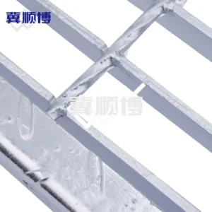
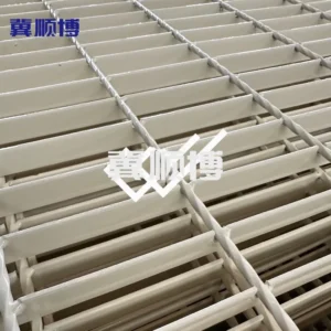
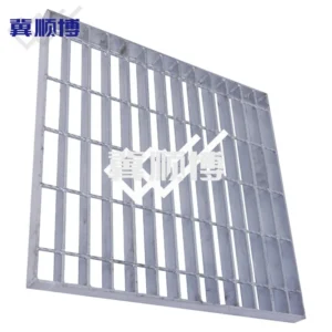
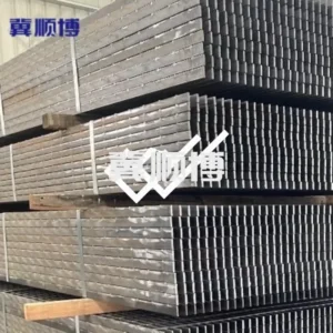
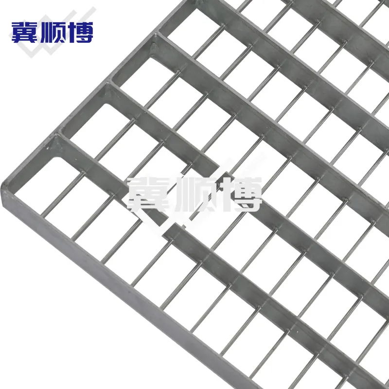
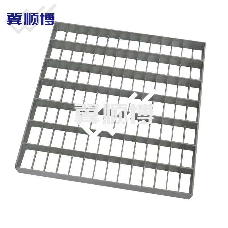
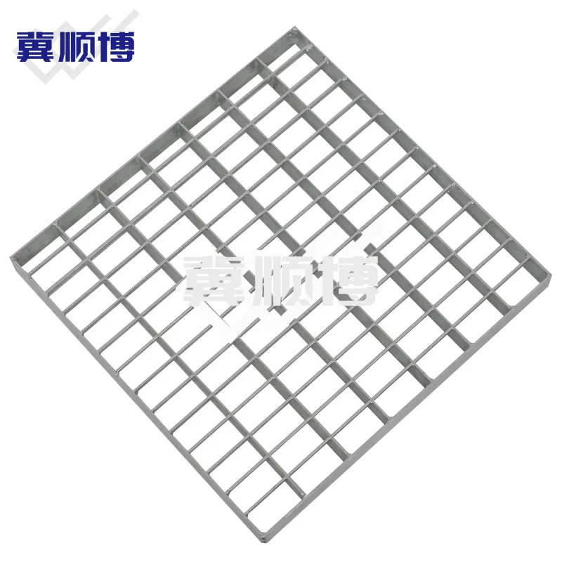
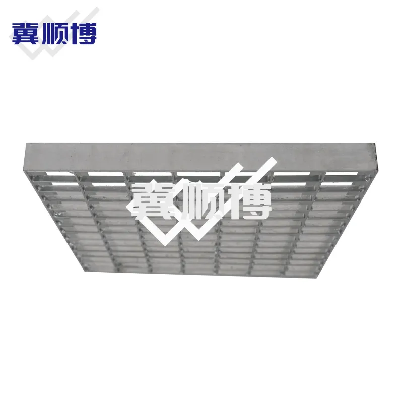
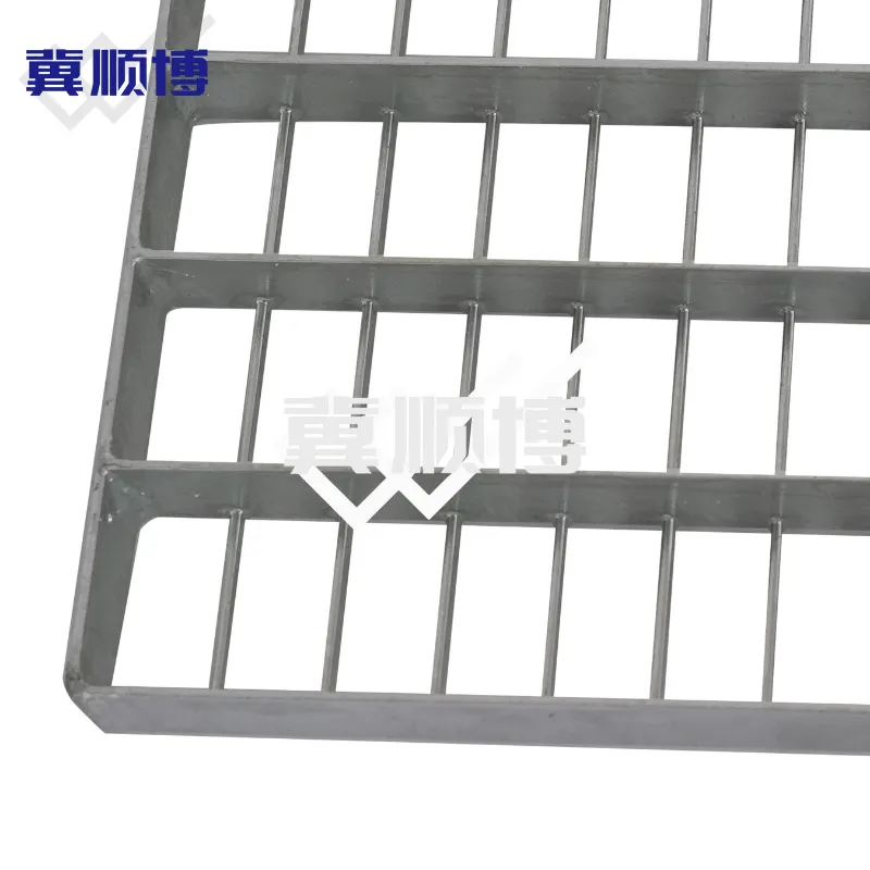
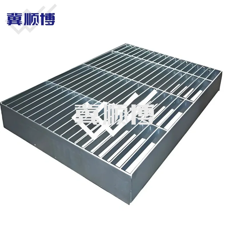
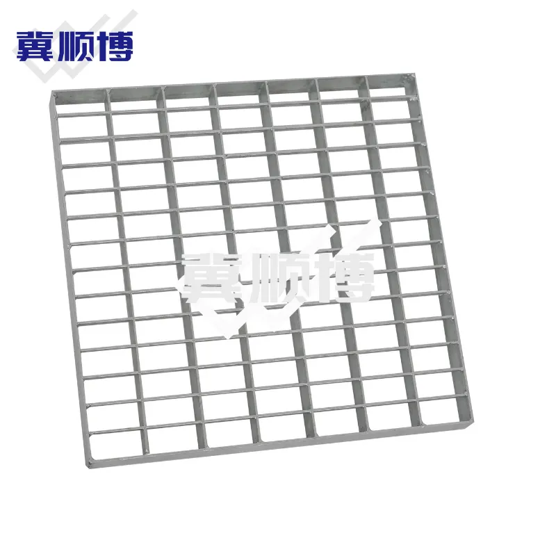
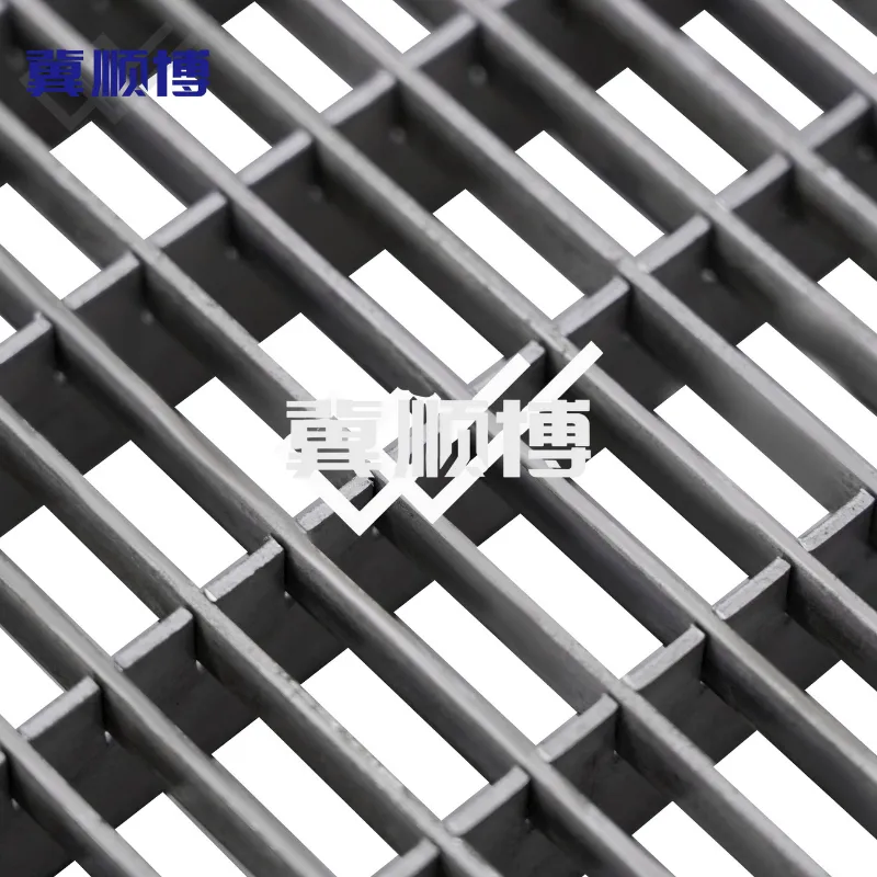
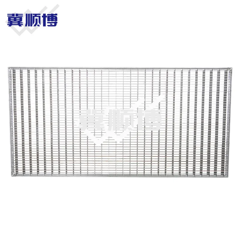
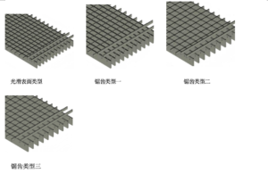
Press-locked carbon steel grating is a high-precision structural flooring system produced by hydraulically forcing cross bars into pre-notched bearing bars. Unlike traditional resistance-welded grating, this process utilizes intense mechanical pressure to create a permanent, friction-fit bond, resulting in a perfectly flush-top surface. Our standard configuration features high-profile bearing bars (e.g., 30x2mm) interlocked with lower-profile cross bars (e.g., 10x2mm). For specialized architectural requirements, we also offer Full-Locked construction, where bearing and cross bars of equal height are intermeshed to create a symmetrical, deep-cell aesthetic.
2. Technical Parameters
| Category | Parameter | Specification / Industry Range | Engineering Notes |
| Material | Steel Grade | Q235B, Q355B, ASTM A36, S275JR | Use Q355B for large-span platforms to optimize load-to-weight efficiency. |
| Bearing Bars | Height / Thickness | 25mm – 150mm / 2.0mm – 8.0mm | Primary load-carrying bars; thickness depends on axle load requirements. |
| Cross Bars | Type & Size | (7x2mm – 20x3mm) | Shorter than bearing bars for standard press-locked; equal height for Full-Locked. |
| Grid Pitch (c/c) | Metric Standards | 33.3×33.3, 33.3×11.1, 44.4×11.1, 44.4×22.2mm(or custom) | 11.1mm clear spacing is mandatory for ADA-compliant pedestrian zones. |
| Mesh Type | NAAMM Designation | 19-P-4, 15-P-4, 11-P-2 | “P” series denotes non-welded, mechanical press-fit construction. |
| Surface Finish | Treatment | Hot-Dip Galvanizing (ISO 1461 / ASTM A123) | Minimum average zinc coating $\geq 85\mu m$ for C4 industrial environments. |
| Standard | Compliance | ANSI/NAAMM MBG 531, DIN 24537 | All fabrication meets structural and safety code requirements. |
| Common hole spacing for bearing bars with a thickness of 2–3 mm. | |||||||||
| Bearing bar/mm | Cross bar/mm | ||||||||
| 11,1 | 11,1 | 16,65 | – | 22,2 | 33,3 | 44,4 | 49,95 | 66,6 | 99,9 |
| 21 | 11,1 | 16,65 | 21,0 | 22,2 | 33,3 | 44,4 | 49,95 | 66,6 | 99,9 |
| 22,1 | 11,1 | 16,65 | 21,0 | 22,2 | 33,3 | 44,4 | 49,95 | 66,6 | 99,9 |
| 33,3 | 11,1 | 16,65 | 21,0 | 22,2 | 33,3 | 44,4 | 49,95 | 66,6 | 99,9 |
| 44,4 | 11,1 | 16,65 | 21,0 | 22,2 | 33,3 | 44,4 | 49,95 | 66,6 | 99,9 |
| 55,5 | 11,1 | 16,65 | 21,0 | 22,2 | 33,3 | 44,4 | 49,95 | 66,6 | 99,9 |
| 66,6 | 11,1 | 16,65 | 21,0 | 22,2 | 33,3 | 44,4 | 49,95 | 66,6 | 99,9 |
| 99,9 | 11,1 | 16,65 | 21,0 | 22,2 | 33,3 | 44,4 | 49,95 | 66,6 | 99,9 |
| Standard bearing bar profile | |||||||||||||||||||
| Bearing Bar 2mm | 20/2 | 25/2 | 30/2 | 35/2 | 40/2 | 45/2 | 50/2 | ||||||||||||
| Bearing Bar 3mm | 20/3 | 25/3 | 30/3 | 35/3 | 40/3 | 45/3 | 50/3 | 60/3 | 70/3 | 80/3 | 90/3 | 100/3 | |||||||
| Bearing Bar 4mm | – | 25/4 | 35/4 | 40/4 | 45/4 | 50/4 | 60/4 | 70/4 | 80/4 | 90/4 | 100/4 | ||||||||
| Bearing Bar 5mm | – | 25/5 | 30/5 | 35/5 | 40/5 | 45/5 | 50/5 | 60/5 | 70/5 | 80/5 | 90/5 | 100/5 | 110/5 | 120/5 | 130/5 | 140/5 | 150/5 | 160/5 | 170/5 |
Engineering Notes:
The mechanical press-fit joint offers superior lateral stability and anti-torsion performance. Since standard cross bars (e.g., 10mm high) are shorter than bearing bars, the structural integrity of the main span is preserved. For architectural louvers or egg-crate ceilings, Full-Locked configurations provide identical visual transparency from both axes. In grain silos, a 11.1mm pitch acts as a high-strength anti-rodent screen while maintaining necessary airflow. For slopes > 10°, serrated bearing bars are recommended to enhance the dynamic coefficient of friction.
3. Product Advantages
1.Precision Geometry: Hydraulic assembly eliminates weld spatter and heat distortion, ensuring perfectly flat panels and seamless alignment during large-scale installation.
2.Superior Lateral Rigidity: Deep-seated cross bars provide a mechanical lock that prevents bearing bar “leaning” or twisting under heavy rolling loads.
3.Flush-Top Surface: The smooth, trippable-free joints are safe for pedestrians, high-heeled shoes, and small-wheeled carts in high-traffic commercial or industrial zones.
4.Architectural Versatility: The symmetrical mesh patterns and clean lines make it suitable for both structural flooring and high-end aesthetic applications like building façades.
4. Applications & Engineering Scenarios
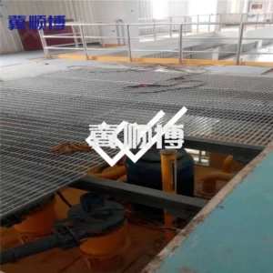
1.Automated Logistics & AGV Platforms: Used in smart warehouses where dimensional precision is critical for the integration of robotic sorting and conveyor systems.
2.Urban Infrastructure (North America/Europe): Specified for ADA-compliant trench covers and subway ventilation grilles requiring a 12.7mm maximum opening width.
3.Power & Chemical Plants (Asia/Middle East): Multi-level access walkways where the bi-directional grid facilitates wash-down and provides clear visibility for maintenance.
4.Architectural Ceilings & Façades: Utilizing Full-Locked patterns for sunshades and interior partitions to achieve a consistent, uniform visual effect.
5. Quality Control & Performance
1.Material Traceability: Every batch includes Mill Test Reports (MTR) verifying yield strength and chemical composition per ASTM/EN standards.
2.Joint Strength Testing: Random shear testing of the press-fit joints to verify that mechanical locks remain rigid under repetitive vibration.
3.Dimensional Accuracy Audit: Strictly monitoring length, width, and diagonal squareness within +/- 3mm to ensure rapid, zero-gap fitment on-site.
4.Zinc Coating Inspection: Magnetic gauge verification per ISO 1461 to ensure the protective layer meets specified lifespan requirements.
6. Factory Customization & Engineering Services
1.Variable Cross Bar Profiles: Customizing cross bar heights (e.g., 7mm, 10mm, 15mm) to balance weight and lateral stiffness.
2.Full-Locked Customization: Providing equal-height bearing and cross bars for specialized “egg-crate” architectural designs.
3.Complex CNC Geometry: Factory-precise cutting for circular,fan-shaped, and irregular shapes to clear piping and structural columns.
4.Technical Load Analysis: Engineering support for span-to-deflection calculations based on specific concentrated or uniform loads.
7. FAQ
Q: Is the cross bar in your press-locked grating notched like the bearing bar?
A: In our standard industrial press-locked grating, the cross bar is a solid flat bar that is not notched. It is hydraulically pressed into the notched bearing bar. This “Semi-Locked” design maintains higher strength in the bearing bar compared to “Full-Locked” types where both bars are notched, making it more efficient for structural load-bearing.
Q: How does press-locked grating prevent object-falls in multi-level industrial platforms?
A: By utilizing our 33.3×11.1mm or 44.4×11.1mm mesh sizes, the clear gap is restricted to approximately 11mm. This exceeds international safety standards (like the 20mm/35mm ball test) by preventing small tools, bolts, or debris from falling through the floor, which is a critical safety requirement for multi-level European and Australian plants.
Q: Can press-locked grating effectively prevent rodent intrusion in grain storage?
A: Yes. The tight-mesh configuration (e.g., 11.1mm pitch) acts as a permanent physical barrier that prevents rats and other pests from entering through ventilation areas. Unlike wire mesh, the rigid flat bars of press-locked grating cannot be gnawed through or easily deformed, ensuring long-term biosecurity.
Q: Why is press-locked stainless steel preferred over welded types for chemical and offshore environments?
A: In saline or acidic environments (C5-M), welds are often the first point of failure due to “intergranular corrosion” caused by heat sensitization. Press-locking is a cold process that preserves the stainless steel’s native chromium-oxide layer, providing significantly better resistance to pitting at the joints.
Q: Is this grating compliant with ADA (Americans with Disabilities Act) standards for North American projects?
A: Yes. When specified with a mesh opening of 1/2 inch (12.7mm) or less in the direction of travel (such as our 11.1mm series), the grating is fully ADA compliant. This ensures a safe, non-slip surface for wheelchairs, walkers, and high-heeled shoe traffic.
Q: Can you engineer press-locked panels to handle heavy forklift traffic in logistics centers?
A: Absolutely. For pneumatic or solid-tire forklifts, we utilize thicker bearing bars (5mm or 6mm) and reinforced banding. The mechanical lock provides the necessary lateral stiffness to prevent bar “tipping” during tight vehicle turns, which is a common failure point in standard welded products.
In summary, Press-Locked Steel Grating offers exceptional precision, flush aesthetics, and robust mechanical locking for demanding applications like automated warehouses, ADA-compliant urban infrastructure, chemical plants, architectural façades, and rodent-proof grain facilities. Its weld-free construction ensures superior joint integrity, easy customization, and reliable performance under heavy loads, vibration, and harsh environments worldwide.